
I "maxed it out" by decoding all the address and data lines, along with all the internal status signals so I could truly see what was going on inside the CPU while it was running a program.
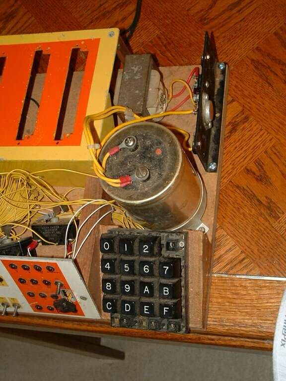
The card cage -- the yellow/orange thing with the slots -- was scavenged from the Ford People Mover at Fairlane, where I worked at the time.
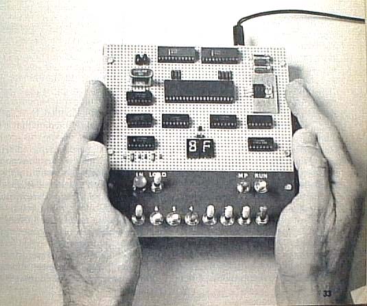
Thanks to Bill Richman for letting me use his scan of the photo from the original construction article. Check out his very cool website!!

The original machine sported one switch and one light emitting diode (LED) as input/output devices. No kidding - the first programming problem was to write a routine which would monitor the switch and turn on the LED if the switch was depressed! (Depresses me just thinking about it!) On my machine, the output LED is in the "box" on the left, and is labeled "Bingo!", kind of a reward for correctly coding the program.
Note the Single Step switch, which is knocked askew on the right side of the panel.

The shiny silverish thing is the crystal which controlled the CPU's clock frequency, which on mine was 4 megahertz. Modern CPUs run at up to about 2 gigahertz -- 500 times faster!
The rest of the chips are for decoding, latching and driving the many LEDs on the front panel.
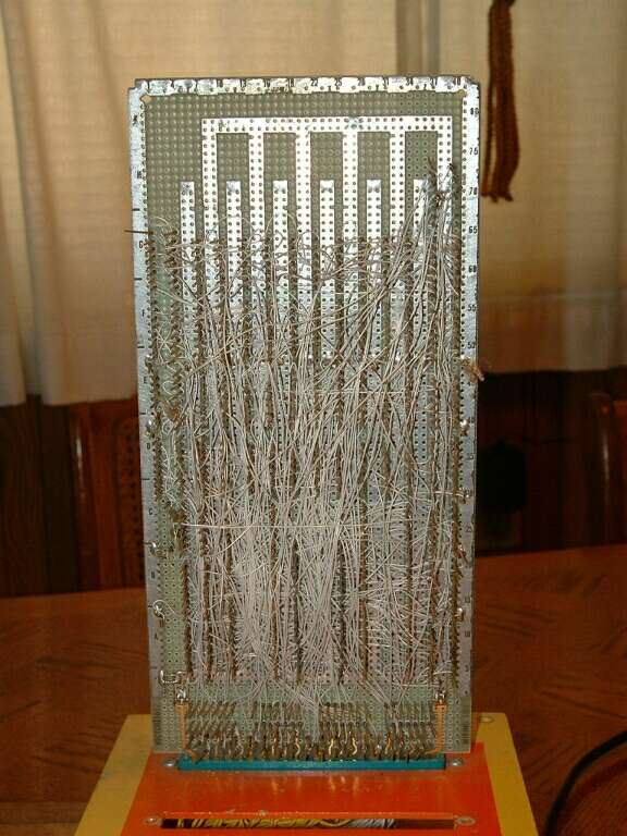
In wire wrapping, about 1 inch of the wire conductor is exposed, and then wrapped about 10 times around the post to form the connection. I used a manual wire wrapping bit inserted into an electric draftsman's eraser to save a little work.
Yes, you CAN make it look neater than this -- but it's literally not recommended. Running the wires parallel and pretty can lead to noise problems in the circuitry.

This was the first upgrade I put in - a "hex" keypad. Without delving into esoteric (and boring) discussions about computers' number handling capability, suffice to say that they don't deal with decimal numbers the way we do. Most computers like to talk "hex" -- short for hexidecimal -- which is base 16. In hex, there are 16 digits rather than the 10 we're accustomed to in decimal, or base 10. That's what the letter keys are for. O thru 9 are represented just as they are in decimal, but 10 through 15 are represented by A to F. It all sounds very strange, but it's very logically attuned to the way computers work with bits and bytes.
The keypad greatly simplified programming, replacing setting 8 toggle switches representing a single digit with a simple keypress. Ah, progress!

The additional slots in the card cage were for future expansion, where I'd hoped to control my whole house (and half of the civilized world) from my computer. It never happened, but I'm still working at the world-domination thing...
So what did I actually DO with this thing? About the most sophisticated use I ever put it to was to wire a relay to the "Bingo!" output, and connected it to my phone line (at work!!!!) to dial telephone numbers. Pretty ironic, considering my general aversion to talking on the telephone, eh? I abandoned my little sweetie when a newer, sexier, pre-fab single board computer came along --- the MOS Technolgy KIM 1.
The ELF was a great learning tool, allowing me to learn programming at the rawest machine code level, where everything is bits, baby, bits. And, with the reconnection of a few wires that have been knocked off in the intervening years, I'd bet she'd still run!